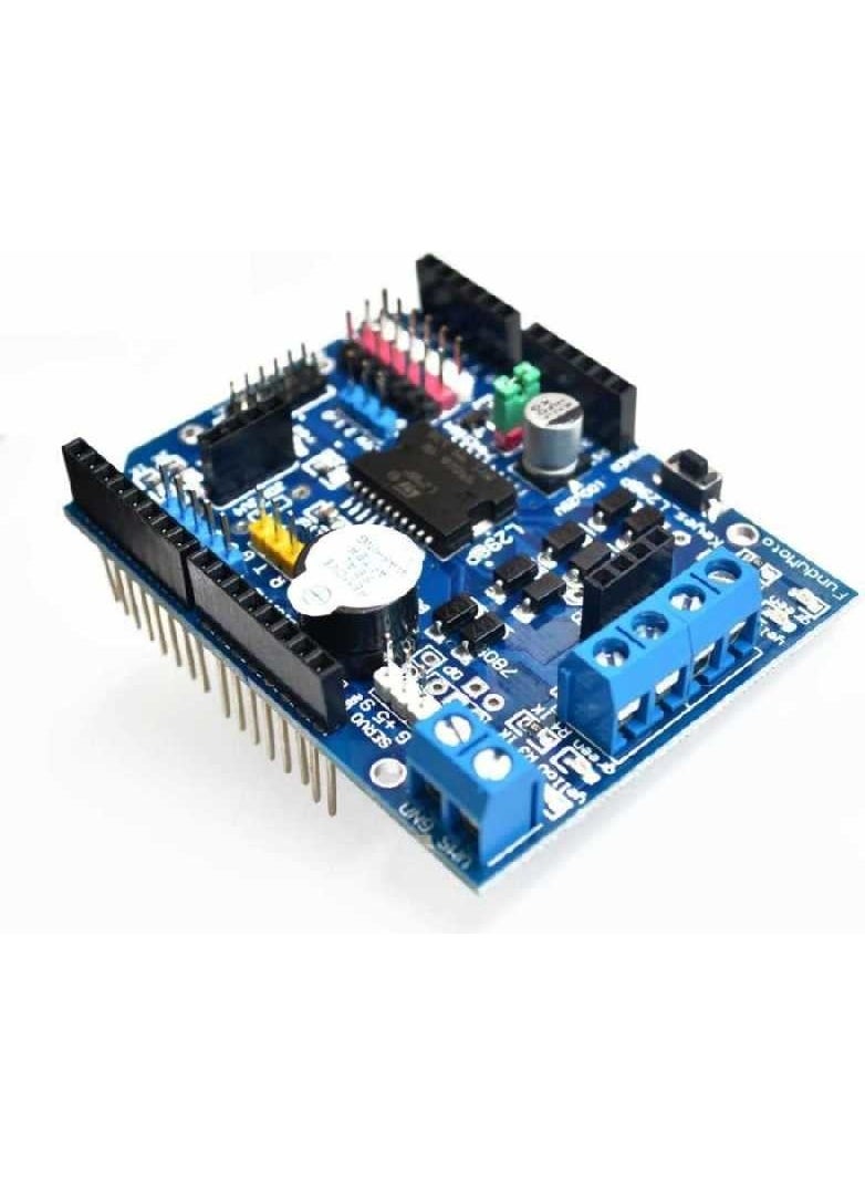
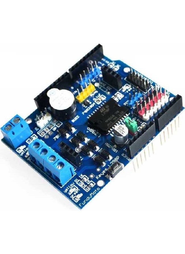
Overview Motor Shield is based on L298 motor driver integrated circuit, a full-bridge motor driver. It can drive two separate 2A DC motors or 1 2A stepper motor. Motor's velocity and directions can be controlled separately. Also there are 6 connectors connected to Arduino analog pins for fast prototyping. Signals can be given with buzzer on card when it is wanted.
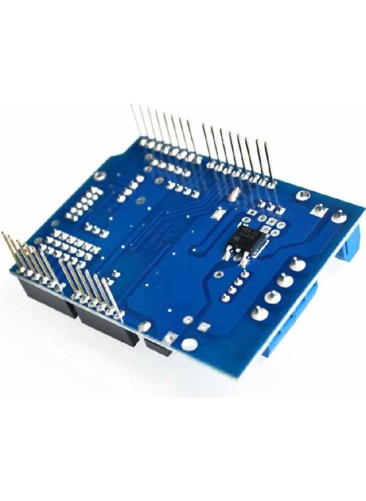
Important P.S: To avoid short circuit between motor terminal on driver and Arduino's USB socket, stackable headers that comes with the product should be stuck to the driver card. This way driver card gets higher and short cut is avoided.
Technical Proportions:
Operating Voltage
| 5V-12V |
Engine Controller
| L298P drives 2 DC motors or 1 stepper motor |
Max. Current
| 2A per channel (with external supply) |
Power:
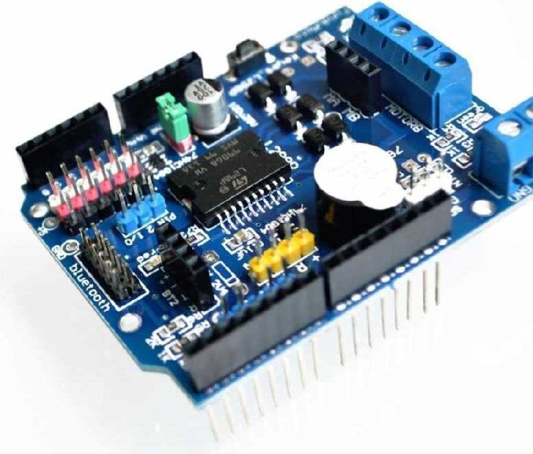
Motor Shield should be only fed with an external source. Because L298 integrated circuit has 2 separate power connections, one for logic and the other for motor feeding. Necessary motor current is usually bigger than max. current that given by USB.
External feeding can be given by an adapter or battery. Adapter can be connected to 2.1mm central positive power socket or VMS and GND terminals on card by being carefull to polarity. But it is advised that power should always be given through terminal on driver. Because when we feed through power socket on Arduino, the motor's current goes through Arduino and reach the driver. Hence Arduino Vin route can take only 1A current, Arduino card might get damaged. That is why external power should always be given through terminal on driver.
VMS terminal on driver is also connected to Arduino Vin pin through header. So when there is a power connection though terminal, Arduino gets power through Vin pin and steps- down it to 5V with its regulator. This way you do not need to use 2 separate power sources. But as you know, Vin pin on Arduino takes input between 7V- 12V. In that case, if our input in driver card is between 5V- 7V since this voltage range is lower than regulator's minimum value, Arduino card do not work properly. To avoid this situation, there is an "OPT" driver card. This jumper connects VMS terminal on driver and Arduino's Vin pin. If voltage on terminal is between 5V- 7V, this jumper disconnects, VMS and Vin get separated and Arduino starts operating with an external 5V. Later card can be returned the way it is used with this jumper. If voltage on terminal is between 7V- 12V, card can be used and jumper can stay as it is.
Input and Output:
Motor shield has two independent channels named A and B. Each channel is controlled with 2 Arduino pins. Shield uses 4 pins in total. By using these channels separately 2 separate DC motor or by using them together 1 unipolar or bipolar stepper motor can be driven.
Shield pin table:
| Function | Channel A Pin | Channel B Pin |
| Direction | D12 | D13 |
| PWM | D10 | D11 |
| Buzzer | D4 | D4 |
Engine Connections:
You can use 2 brushed DC motor by connecting them to Motor A and Motor B terminals on the card. By making DIR A and DIR B pins HIGH or LOW, you can control direction of motors, by changing PWM A and PWM B pins fullnes rate, you can control velocity of motors.
 Free & Easy Returns
 Best Deals


![/fashion-men/jack_jones/?sort[by]=popularity&sort[dir]=desc&limit=50](https://a.nooncdn.com/cms/pages/20240305/4ef48af441e2b44cea1673cd2e4aff67/en_dk-men-brands-04.png)


![/fashion-men/seventy_five/?sort[by]=popularity&sort[dir]=desc&limit=50](https://a.nooncdn.com/cms/pages/20240305/4ef48af441e2b44cea1673cd2e4aff67/en_dk-womens-new-brands-01.png)
![/fashion-men/skechers/?sort[by]=popularity&sort[dir]=desc&limit=50](https://a.nooncdn.com/cms/pages/20240305/4ef48af441e2b44cea1673cd2e4aff67/en_dk-womens-new-brands-02.png)


![/fashion-women/mango/?sort[by]=popularity&sort[dir]=desc&limit=50](https://a.nooncdn.com/cms/pages/20240305/4ef48af441e2b44cea1673cd2e4aff67/en_dk-women-brands-05.png)
![/fashion-women/guess/?sort[by]=popularity&sort[dir]=desc&limit=50](https://a.nooncdn.com/cms/pages/20240305/4ef48af441e2b44cea1673cd2e4aff67/en_dk-women-brands-09.png)


![/fashion-women/ella/?sort[by]=popularity&sort[dir]=desc&limit=50](https://a.nooncdn.com/cms/pages/20241812/en_dk-nav-brands-01.png)
![/fashion-women/skechers/?sort[by]=popularity&sort[dir]=desc&limit=50](https://a.nooncdn.com/cms/pages/20241812/en_dk-nav-brands-02.png)


![/fashion/view-all-kids-clothing/nike/?sort[by]=popularity&sort[dir]=desc&limit=50](https://a.nooncdn.com/cms/pages/20240911/nav-web/en_mb_uae_brand-01.png)
![/fashion/view-all-kids-clothing/disney/disney_minnie_mouse/disney_frozen/disney_princess/disney_mickey_mouse/disney_baby/?sort[by]=popularity&sort[dir]=desc&limit=50](https://a.nooncdn.com/cms/pages/20240911/nav-web/en_mb_uae_brand-03.png)


![/fashion/view-all-kids-clothing/new_balance/?sort[by]=popularity&sort[dir]=desc&limit=50](https://a.nooncdn.com/cms/pages/20240911/nav-web/en_mb_uae_brand-11.png)


![/baby-products/momcozy/?f[partner][]=p_9404&sort[by]=popularity&sort[dir]=desc&limit=50&page=1&isCarouselView=false&av=0](https://a.nooncdn.com/cms/pages/20241031/navrev-baby/en_uae_dk-nav-04.png)


![/music-movies-and-tv-shows/musical-instruments-24670/pianos-keyboards-synthesizers/roland/?sort[by]=popularity&sort[dir]=desc&limit=50&page=1&isCarouselView=false](https://f.nooncdn.com/cms/pages/20250407/books-nav/en_uae_dk-nav-brands-05.png)
![/music-movies-and-tv-shows/musical-instruments-24670/pianos-keyboards-synthesizers/mike_music/?sort[by]=popularity&sort[dir]=desc&limit=50&page=1&isCarouselView=false](https://f.nooncdn.com/cms/pages/20250407/books-nav/en_ksa_dk-nav-brands-04.png)


