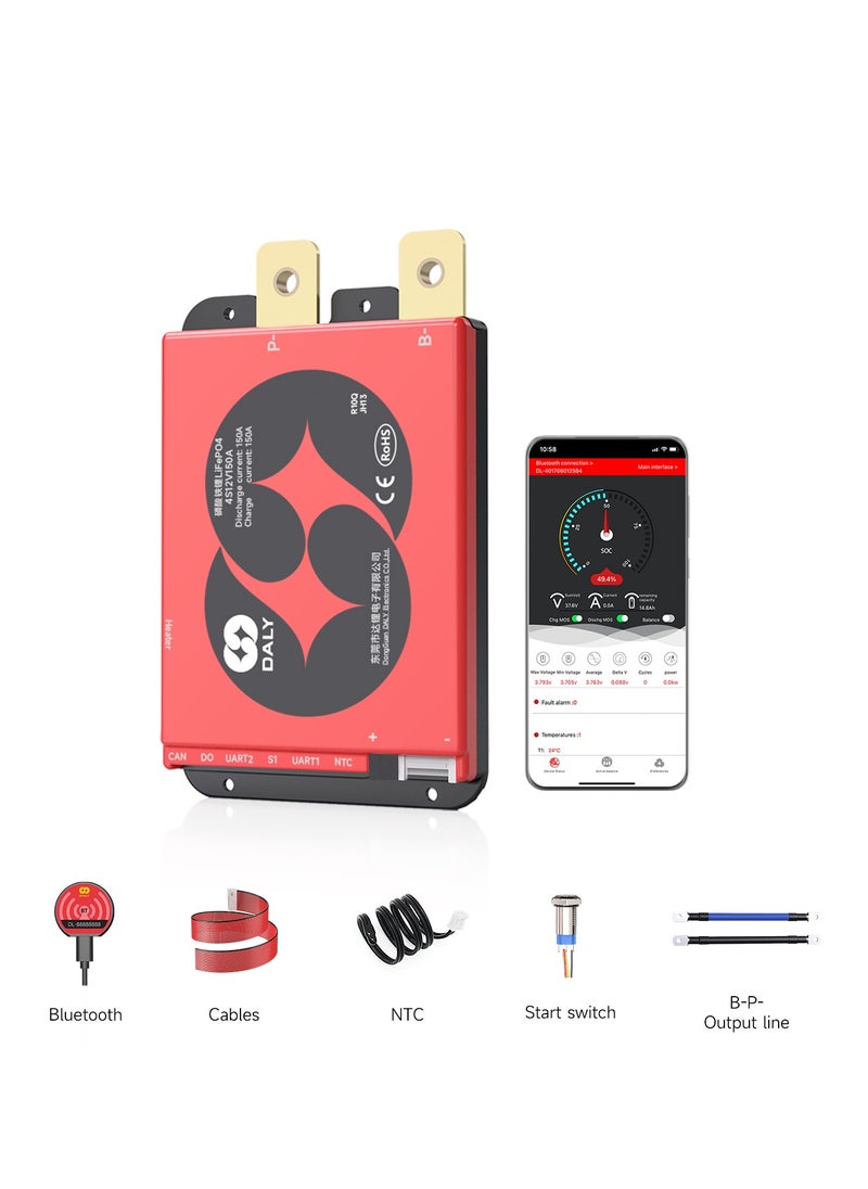
Overview1.Sepecification
Number of strings: 4S /8S
Battery type: LiFePO4
Current range: 150A
Peek Overcurrent: 2000A
Communication function: UART/CAN
Software function: APP/PC/IOT
Advantage function: Bluetooth & Forced Start Switch 2-in-1 Design
Standard accessories: BT Switch module
Wire specification: 24AWG/450mm
NTC length: 28AWG/250mm
Integrated heating module: 25A heating current
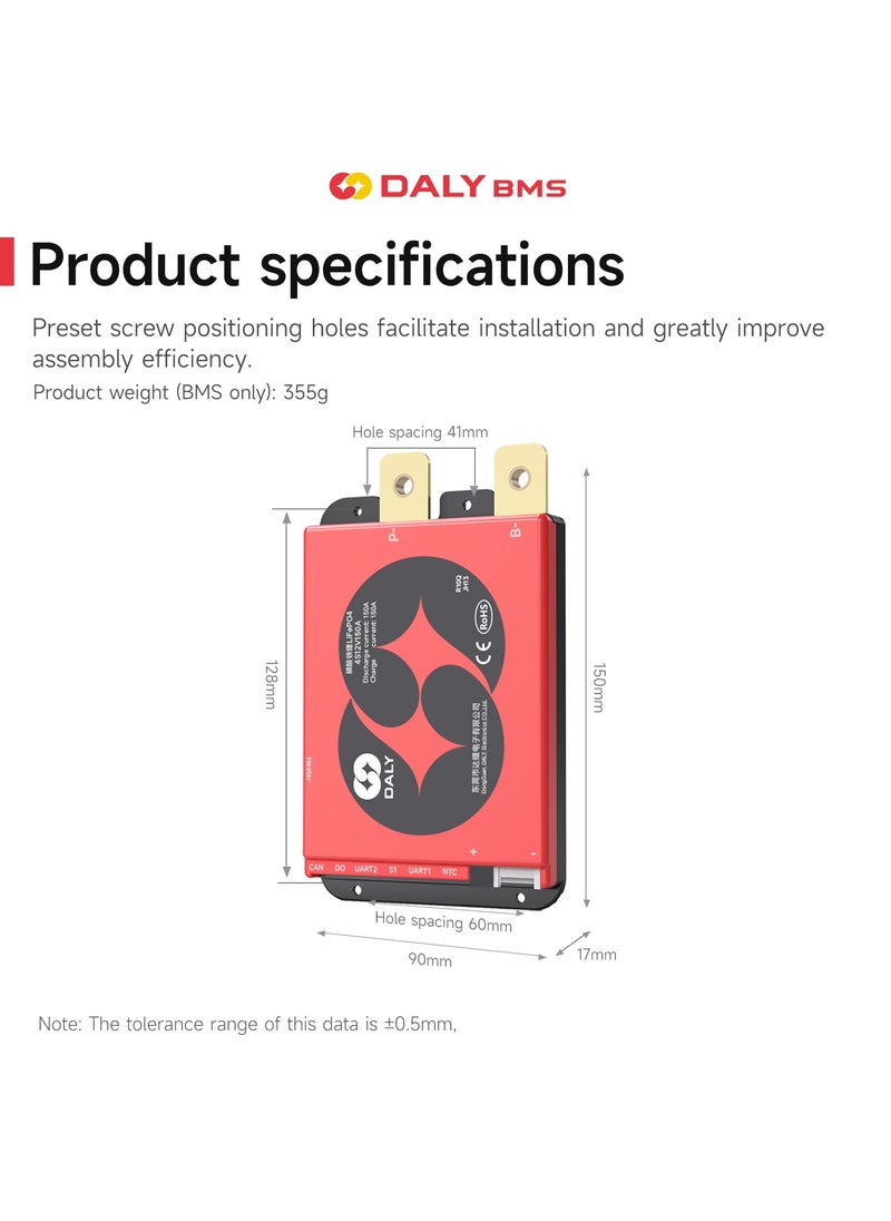
2. Product Size(Data tolerance range ±0.5mm)
Product Size: L * W * H (mm) = 151*90*26mm, 480g
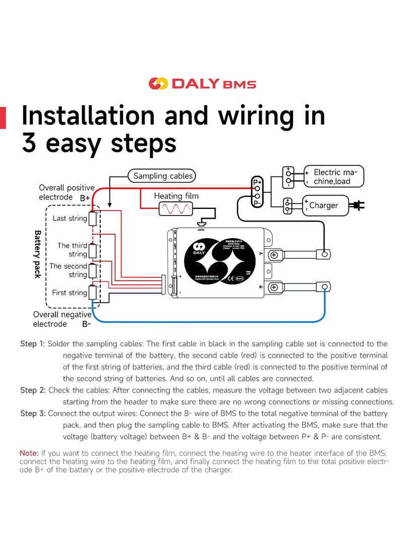
3. BMS Wiring and Removal Instructions
Wiring the BMS:
1. Connect the B- Cable:
- Begin by connecting the B- cable of the BMS to the total negative pole of the battery pack.
2. Cell Wiring:
- Start from the thin black cable connected to B-.
- The second wire connects to the positive terminal of the first battery cell.
- Continue connecting each cell’s positive terminal in sequence.
- Finally, insert the B+ cable into the BMS and connect it to the positive terminal of the last cell.
3. Verify the Setup:
- After completing the wiring, check if the green indicator light is on.
- Use the Bluetooth app or PC software to check for any fault alarms.
- Measure the voltages at B+ and B-. They should match the voltages of P+ and P-. If the voltages match, the BMS is functioning properly. If not, recheck and rewire according to the steps above.
Removing the BMS:
1. Turn Off the Load Power:
- Turn off the load power switch to prevent any electrical issues during disconnection.
2. Disconnect the Cables:
- If there are two cables, start by pulling out the high-voltage cable first, followed by the low-voltage cable.
- Then remove the P- cable from the BMS.
3. Final Removal of B- Cable:
- Finally, disconnect the power line B- to complete the BMS removal process.
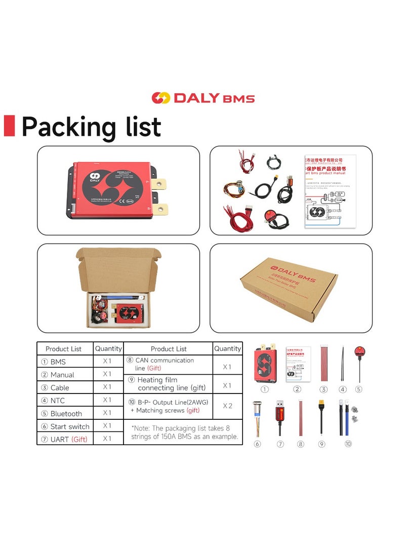
Packing List:
Smart Truct Starts BMS *1
B-P-Output cables *1 set
Screw *2
B+ Cable *1
NTC(2 ways) *1
Sampling Cable *1
CAN/485 5pin cable *1
BT switch *1
BT Module *1
Heating film connecting cable *1
Instruction card *1
 Free & Easy Returns
 Best Deals


![/fashion-men/jack_jones/?sort[by]=popularity&sort[dir]=desc&limit=50](https://a.nooncdn.com/cms/pages/20240305/4ef48af441e2b44cea1673cd2e4aff67/en_dk-men-brands-04.png)


![/fashion-men/seventy_five/?sort[by]=popularity&sort[dir]=desc&limit=50](https://a.nooncdn.com/cms/pages/20240305/4ef48af441e2b44cea1673cd2e4aff67/en_dk-womens-new-brands-01.png)
![/fashion-men/skechers/?sort[by]=popularity&sort[dir]=desc&limit=50](https://a.nooncdn.com/cms/pages/20240305/4ef48af441e2b44cea1673cd2e4aff67/en_dk-womens-new-brands-02.png)


![/fashion-women/mango/?sort[by]=popularity&sort[dir]=desc&limit=50](https://a.nooncdn.com/cms/pages/20240305/4ef48af441e2b44cea1673cd2e4aff67/en_dk-women-brands-05.png)
![/fashion-women/guess/?sort[by]=popularity&sort[dir]=desc&limit=50](https://a.nooncdn.com/cms/pages/20240305/4ef48af441e2b44cea1673cd2e4aff67/en_dk-women-brands-09.png)


![/fashion-women/ella/?sort[by]=popularity&sort[dir]=desc&limit=50](https://a.nooncdn.com/cms/pages/20241812/en_dk-nav-brands-01.png)
![/fashion-women/skechers/?sort[by]=popularity&sort[dir]=desc&limit=50](https://a.nooncdn.com/cms/pages/20241812/en_dk-nav-brands-02.png)


![/fashion/view-all-kids-clothing/nike/?sort[by]=popularity&sort[dir]=desc&limit=50](https://a.nooncdn.com/cms/pages/20240911/nav-web/en_mb_uae_brand-01.png)
![/fashion/view-all-kids-clothing/disney/disney_minnie_mouse/disney_frozen/disney_princess/disney_mickey_mouse/disney_baby/?sort[by]=popularity&sort[dir]=desc&limit=50](https://a.nooncdn.com/cms/pages/20240911/nav-web/en_mb_uae_brand-03.png)


![/fashion/view-all-kids-clothing/new_balance/?sort[by]=popularity&sort[dir]=desc&limit=50](https://a.nooncdn.com/cms/pages/20240911/nav-web/en_mb_uae_brand-11.png)


![/music-movies-and-tv-shows/musical-instruments-24670/pianos-keyboards-synthesizers/chloris/?sort[by]=popularity&sort[dir]=desc&limit=50&page=1&isCarouselView=false](https://f.nooncdn.com/cms/pages/20250407/books-nav/en_uae_dk-nav-brands-04.png)
![/music-movies-and-tv-shows/musical-instruments-24670/pianos-keyboards-synthesizers/roland/?sort[by]=popularity&sort[dir]=desc&limit=50&page=1&isCarouselView=false](https://f.nooncdn.com/cms/pages/20250407/books-nav/en_uae_dk-nav-brands-05.png)
![/music-movies-and-tv-shows/musical-instruments-24670/pianos-keyboards-synthesizers/donner/?sort[by]=popularity&sort[dir]=desc&limit=50&page=1&isCarouselView=false](https://f.nooncdn.com/cms/pages/20250407/books-nav/en_uae_dk-nav-brands-06.png)
![/music-movies-and-tv-shows/musical-instruments-24670/pianos-keyboards-synthesizers/korg/?sort[by]=popularity&sort[dir]=desc&limit=50&page=1&isCarouselView=false](https://f.nooncdn.com/cms/pages/20250407/books-nav/en_uae_dk-nav-brands-07.png)