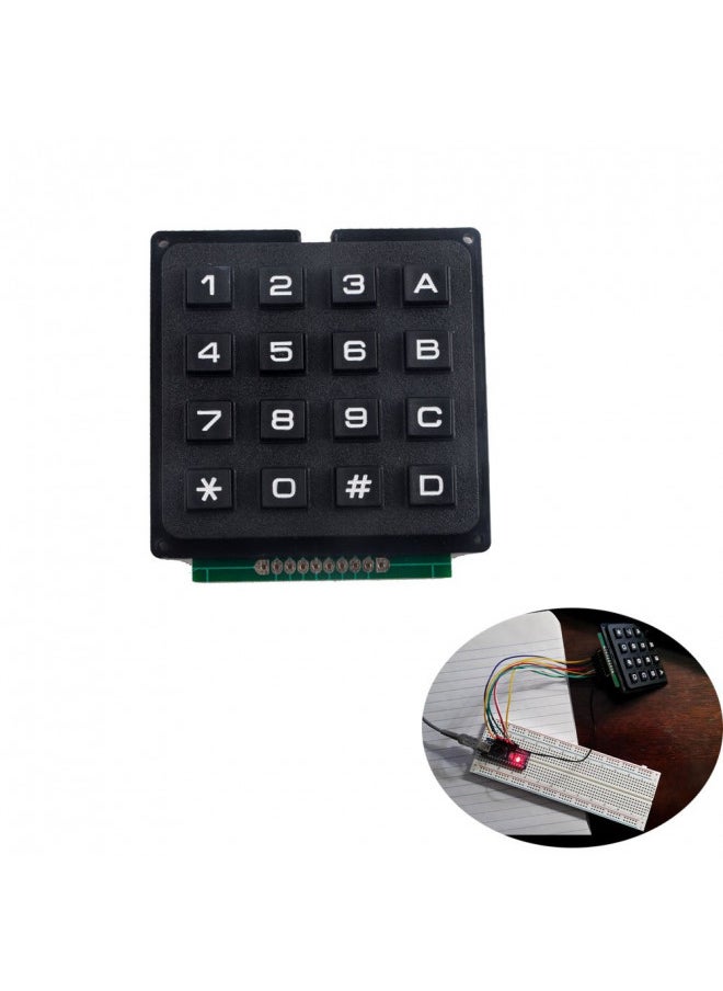
The Keypad library allows development board to read a matrix type keypad. 4×4 numeric keypads are widely used in project which requires the user to give command to the system or to feed in some data.
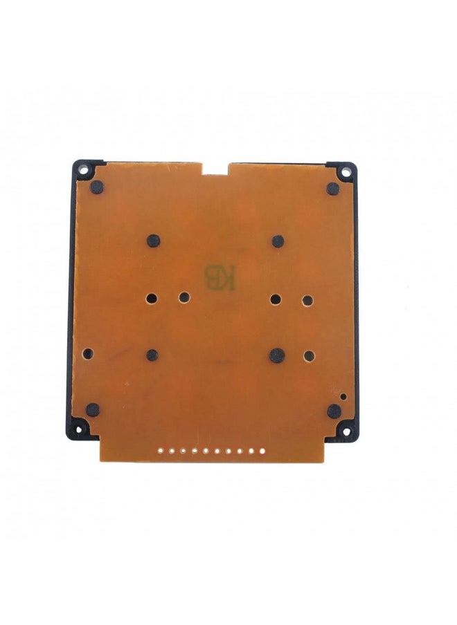
You don't need the outer two pins on the left and right for wiring. It's the inner 8 pins that matter.
If you solder on a header, we highly recommend laying down some flux on the pads first, inserting the header pins, then soldering
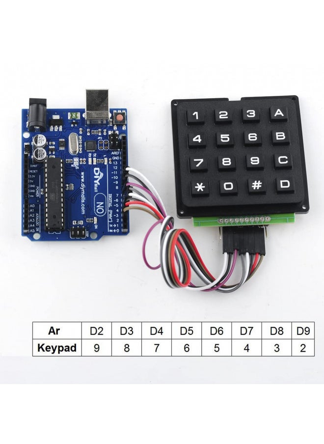
The standard Keypad library for arduino works out of the box with this particular device.
If you have any problem, please do as follow: click "DIYmalls"(you can find "Sold by DIYmalls" under Buy Now button), in the new page, click "Ask a question".
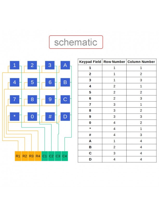
OverviewDescription: -The Keypad library allows your developmment board to read a matrix type keypad. 4×4 numeric keypads are most widely used in project which requires user or operator to give command to system or to feed in some data. - Keyboard for the pin interface.4X4 design, 10 numeric keys, 4 English keys,2 function keys. There is a switch connecting each row and column. So the combinations of rows and columns makes up the 16 inputs. - Circuit board is PCB double-panel There is a switch connecting each row and column. So the combinations of rows and columns makes up the 16 inputs. So, try to imagine this. Initially all the switch are open (not connected). When you pressed either one buttons, the switch is now closed (connected). As you can see, now there is a connection between the row and column. Now we know how a matrix keypad works, but how do we relate it with our microcontroller ? So we connect the first 4 pins to the column as INPUT. The other 4 pins is connected to the row as OUTPUT. The input meant that is the input to the microcontroller while output is the output from the microcontroller. Note that the input to the microcontroller has to connect to pull high resistor, or you can use the internal pull up from Arduino itself. For a 4×4 matrix keypad, usually it has 8 pins on it. How do we know which pins are associate to which rows and columns? A digital multimeter (DMM) would ease your job. Turn your DMM to connectivity mode. Now put one of your meter probe to the first pin and the other one to the fifth pin. Try to press the button and see which button would gives you the beep sound. Next, try to probe to the sixth pin and press other button. Keep trying and you would understand the connection behind the keypad. Finally we have reached to the software part.. Package Included : 1 x 16 keys keypad
Cart Total 73.00
We're Always Here To Help
Reach out to us through any of these support channels
'`noon`', the 'noon device', 'noon east', 'east' and the 'east device' are trade marks or registered trade marks of Noon AD Holdings LTD. in the UAE and other countries
 Free & Easy Returns
 Best Deals


![/fashion-men/jack_jones/?sort[by]=popularity&sort[dir]=desc&limit=50](https://a.nooncdn.com/cms/pages/20240305/4ef48af441e2b44cea1673cd2e4aff67/en_dk-men-brands-04.png)


![/fashion-men/seventy_five/?sort[by]=popularity&sort[dir]=desc&limit=50](https://a.nooncdn.com/cms/pages/20240305/4ef48af441e2b44cea1673cd2e4aff67/en_dk-womens-new-brands-01.png)
![/fashion-men/skechers/?sort[by]=popularity&sort[dir]=desc&limit=50](https://a.nooncdn.com/cms/pages/20240305/4ef48af441e2b44cea1673cd2e4aff67/en_dk-womens-new-brands-02.png)


![/fashion-women/mango/?sort[by]=popularity&sort[dir]=desc&limit=50](https://a.nooncdn.com/cms/pages/20240305/4ef48af441e2b44cea1673cd2e4aff67/en_dk-women-brands-05.png)
![/fashion-women/guess/?sort[by]=popularity&sort[dir]=desc&limit=50](https://a.nooncdn.com/cms/pages/20240305/4ef48af441e2b44cea1673cd2e4aff67/en_dk-women-brands-09.png)


![/fashion-women/ella/?sort[by]=popularity&sort[dir]=desc&limit=50](https://a.nooncdn.com/cms/pages/20241812/en_dk-nav-brands-01.png)
![/fashion-women/skechers/?sort[by]=popularity&sort[dir]=desc&limit=50](https://a.nooncdn.com/cms/pages/20241812/en_dk-nav-brands-02.png)


![/fashion/view-all-kids-clothing/nike/?sort[by]=popularity&sort[dir]=desc&limit=50](https://a.nooncdn.com/cms/pages/20240911/nav-web/en_mb_uae_brand-01.png)
![/fashion/view-all-kids-clothing/disney/disney_minnie_mouse/disney_frozen/disney_princess/disney_mickey_mouse/disney_baby/?sort[by]=popularity&sort[dir]=desc&limit=50](https://a.nooncdn.com/cms/pages/20240911/nav-web/en_mb_uae_brand-03.png)


![/fashion/view-all-kids-clothing/new_balance/?sort[by]=popularity&sort[dir]=desc&limit=50](https://a.nooncdn.com/cms/pages/20240911/nav-web/en_mb_uae_brand-11.png)


![/music-movies-and-tv-shows/musical-instruments-24670/pianos-keyboards-synthesizers/chloris/?sort[by]=popularity&sort[dir]=desc&limit=50&page=1&isCarouselView=false](https://f.nooncdn.com/cms/pages/20250407/books-nav/en_uae_dk-nav-brands-04.png)
![/music-movies-and-tv-shows/musical-instruments-24670/pianos-keyboards-synthesizers/roland/?sort[by]=popularity&sort[dir]=desc&limit=50&page=1&isCarouselView=false](https://f.nooncdn.com/cms/pages/20250407/books-nav/en_uae_dk-nav-brands-05.png)
![/music-movies-and-tv-shows/musical-instruments-24670/pianos-keyboards-synthesizers/donner/?sort[by]=popularity&sort[dir]=desc&limit=50&page=1&isCarouselView=false](https://f.nooncdn.com/cms/pages/20250407/books-nav/en_uae_dk-nav-brands-06.png)
![/music-movies-and-tv-shows/musical-instruments-24670/pianos-keyboards-synthesizers/korg/?sort[by]=popularity&sort[dir]=desc&limit=50&page=1&isCarouselView=false](https://f.nooncdn.com/cms/pages/20250407/books-nav/en_uae_dk-nav-brands-07.png)